
flexible PCB manufacture
A PCB is a vital component in any electronic product. It provides a means to connect components together in a compact circuit design that is easy to manufacture and install. Modern electronic products are highly complex, with multiple functions and moving parts. These devices must be small, light in weight, and durable enough to withstand mechanical stress and heat. At the same time, they must be sleek and attractive to appeal to consumers. To meet these demands, PCBs have been designed to be flexible in nature. Flexible Printed Circuit Boards (FPCB) offer a unique solution, combining the reliability of rigid circuit boards with the flexibility of FFCs.
The first flexible pcb manufacture concept was invented at the start of the 20th century, by German inventor Albert Hanson. However, the world was not yet ready to accept this technology and it did not see wide-spread use until the 1940s. During this time, it was used by the US Army to make proximity fuses for military applications.
Since then, many advancements have been made in PCB technology and manufacturing processes. Today, PCBs are manufactured by a combination of human and machine-based steps. There is software to create the circuit design, special printers that apply a solder paste, and machines that place and melt the solder onto the circuit board. During the 1980’s, surface mount technology was introduced, making the assembly process even faster and more compact.
How has flexible PCB manufacture evolved over the years?
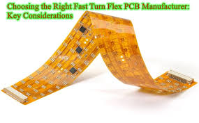
Rigid-flex PCBs are becoming increasingly popular in a number of industries. Some of the most important markets include medical, aerospace, and consumer electronics. This is because the flexibility of flex circuits makes them well-suited to these types of applications. This is due to the fact that a flexible circuit board can be bent, curved, or folded in a number of different ways. In addition, it can be molded into a variety of three-dimensional shapes for different applications.
A flex circuit is typically comprised of four major layers: the copper layer, the insulating layer, the adhesive layer, and the cover layer. The conductor metal is typically copper, as it offers superb electric properties at a relatively low cost. It also dissipates heat quickly. The insulating layer is usually a polyimide film or similar material. The adhesive layer is either tin or soft gold, depending on the application.
The cover layer is a layer of protective material that covers the conductive copper layer and the adhesive. It can be laminated to the copper layer or applied by sputtering. Alternatively, newer fabrication processes by materials vendors now allow for adhesiveless lamination of rolled annealed copper. This is an alternative to the traditional epoxy or acrylic bonding process, which has high tooling costs. Lastly, the flex circuit is cut out using a blanking knife or hydraulic punch and die set for high-volume production runs. For prototype and low-volume production, the blanking knife is simply a long razor blade, shaped to fit the flex circuit outline, and affixed into a routed slot on a base material such as MDF or plywood.


