
Troubleshoot Issues on an RF Board
RF circuits are found in everything from mobile phones to radar systems. They require special considerations for proper design and construction, as they can be prone to signal interference and loss. As such, understanding how to troubleshoot issues on an RF board is vital for making sure that your electronic products are working properly.
Unlike standard PCBs, RF boards are designed to handle high-frequency signals in the megahertz (MHz) to gigahertz (GHz) range. The material used for an RF circuit board is also different, as it must be able to absorb and conduct these frequencies without losing quality. This requires the use of materials that have a low dielectric constant, like FR-4 or Rogers. Other factors include careful component placement and assembly best practices.
These factors can cause many different problems, including excessive heat generation and signal distortion. In order to keep components cool, rf board often use thermal vias and heat sinks. It is also important to make sure that the stack-up, or arrangement of layers, is optimized for performance. A poor stack-up can lead to unwanted inductance and capacitance, which can delay or distort signals.
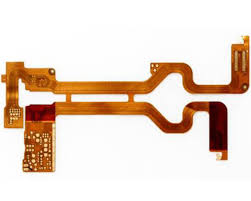
How to Troubleshoot Issues on an RF Board
One of the easiest ways to troubleshoot an RF board is to visually compare it to another identical board. The two should be almost identical, and any differences can point to a specific problem. For example, a brown burn mark on an RF board can indicate that a physical component has overheated. Other signs of physical component error include bulging components or dull-looking connections.
In addition to visual comparisons, it is also useful to run a power integrity test. This involves measuring the voltage of the power rails with a multimeter device. The readings should match the input and output values expected at the component, as well as the power supply’s maximum rating. If the readings display 0 volts, there may be a short circuit along the power rail, which could lead to overheating.
Once the RF board is fabricated, it must be assembled and soldered into place. As with any PCB, the fabrication process can be susceptible to errors. It is crucial that manufacturers follow best practices when using soldering techniques, such as wave or reflow. RF components are sensitive, and any small mistakes can cause major problems.
After assembly, the RF board must be tested for electrical characteristics. This can be done with a multimeter, which will read the power values and display a waveform. It is also possible to perform signal probing, which involves using a probe to test individual components on the board for voltage tests and waveform capture.
To troubleshoot an RF board, it is vital to consult the datasheet for that particular board. The datasheet will provide valuable insights and manufacturer-recommended solutions to common problems. By following these simple steps, you can ensure that your RF circuit board is functioning properly. With this knowledge, you can confidently develop and manufacture your next electronics product. This will allow you to focus on what matters most: designing a great product.