
Flex Circuit PCBs From Electromagnetic Interference
Many electronics are sensitive to absorbing or emitting electromagnetic interference (EMI) which can negatively impact performance and in extreme cases prevent the device from functioning at all. The primary method to mitigate this interference is to incorporate EMI shielding into the design, a crucial step in ensuring that flex circuit PCBs meet industry standards and are safe for consumer use.
There are several ways to incorporate effective EMI shielding into a flex PCB. One way is to use nickel coatings to create a conductive layer that effectively blocks unwanted electromagnetic signals. Another method is to utilize conductive polymers, which offer high electrical conductivity and can be patterned to specific areas of the board. This type of shielding can be applied in combination with other materials to ensure a highly functional and robust flexible circuit.
In addition to using EMI shielding, it is also important to make sure that the board has the right traces and impedances to maintain signal integrity and reduce the potential for EMI interference. This can be achieved by maintaining strict tolerances during the manufacturing process for material preparation, imaging, plating, and lamination. This ensures that the traces have consistent dimensions and impedance values, and will not be affected by mechanical stress during handling or assembly.
Another technique for limiting EMI is to use filters, such as capacitors and inductors, to suppress unwanted frequencies. Decoupling capacitors can be used to filter out high-frequency noise from power lines, while ferrite beads can limit EMI on signal traces. These filters can be combined with other EMI mitigation techniques, such as maintaining consistent trace widths and spacing to achieve controlled impedance and avoiding sharp bends which can cause interference.
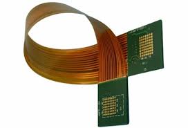
Protecting Flex Circuit PCBs From Electromagnetic Interference
The effectiveness of EMI shielding can be further improved by utilizing the right materials for the substrate and the cover-lay. The best EMI shielding materials will have a low dielectric constant and low loss tangent to minimize signal delay and attenuation. They should also be able to withstand the rigorous environmental tests required by various industries.
It is also important to use a low-resistance copper for the grounding layer of the flex PCB to minimize signal attenuation. In some cases, it may be necessary to increase the thickness of the grounding layer to reduce EMI interference. However, this should be done cautiously since it can negatively impact the flex circuit pcb minimum bend capacity and overall structural rigidity.
The most effective EMI shielding solution for a flex circuit is a shielding film that is pasted on the flex or flex-rigid PCB using heat and pressure. This shielding film has a three-layer makeup that includes a frictionless black insulation layer, a metallic disposition layer, and an electrically conductive adhesive layer that is melted and fused to the cover-lay during the lamination process. This is a cost-effective method that can be customized to suit individual project requirements. It is an ideal option for high-speed traces in medical, industrial, and other mission-critical applications.